Friday, January 8, 2016

What is the Difference of VPN IPSec Tunnel Mode and IPSec Transport Mode

IPSec’s protocol objective is to provide security services for IP packets such as encrypting sensitive data, authentication, protection against replay and data confidentiality.

As outlined in our IPSec protocol article, Encapsulating Security Payload (ESP) and Authentication Header (AH) are the two IPSec security protocols used to provide these security services.  Analysing  the ESP and AH protocols is out of this article’s scope, however you can turn to our IPSec article where you’ll find an in-depth analysis and packet diagrams to help make the concept clear.
 
IPSec Modes –Tunnel Mode & Transport Mode

IPSec can be configured to operate in two different modes, Tunnel and Transport mode. Use of each mode depends on the requirements and implementation of IPSec.

IPSec Tunnel Mode

IPSec tunnel mode is the default mode. With tunnel mode, the entire original IP packet is protected by IPSec. This means IPSec wraps the original packet, encrypts it, adds a new IP header and sends it to the other side of the VPN tunnel (IPSec peer).

Tunnel mode is most commonly used between gateways (Cisco routers or ASA firewalls), or at an end-station to a gateway, the gateway acting as a proxy for the hosts behind it.

Tunnel mode is used to encrypt traffic between secure IPSec Gateways, for example two Cisco routers connected over the Internet via IPSec VPN. Configuration and setup of this topology is extensively covered in our Site-to-Site IPSec VPN article. In this example, each router acts as an IPSec Gateway for their LAN, providing secure connectivity to the remote network:
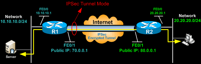
IPSec Tunnel Mode
Another example of tunnel mode is an IPSec tunnel between a Cisco VPN Client and an IPSec Gateway (e.g ASA5510 or PIX Firewall). The client connects to the IPSec Gateway. Traffic from the client is encrypted, encapsulated inside a new IP packet and sent to the other end. Once decrypted by the firewall appliance, the client’s original IP packet is sent to the local network.

In tunnel mode, an IPSec header (AH or ESP header) is inserted between the IP header and the upper layer protocol. Between AH and ESP,  ESP is most commonly used in IPSec VPN Tunnel configuration.

The packet diagram below illustrates IPSec Tunnel mode with ESP header:

IPSec Transport Tunnel   
 The packet diagram below illustrates IPSec Tunnel mode with AH header:

IPSec Tunnel mode with AH header

The AH can be applied alone or together with the ESP, when IPSec is in tunnel mode. AH’s job is to protect the entire packet. The AH does not protect all of the fields in the New IP Header because some change in transit, and the sender cannot predict how they might change. The AH protects everything that does not change in transit. AH is identified in the New IP header with an IP protocol ID of 51.

IPSec Transport Mode

IPSec Transport mode is used for end-to-end communications, for example, for communication between a client and a server or between a workstation and a gateway (if the gateway is being treated as a host).  A good example would be an encrypted Telnet or Remote Desktop session from a workstation to a server.

IPSec Encrypted Tunnel
Transport mode provides the protection of our data, also known as IP Payload, and consists of TCP/UDP header + Data, through an AH or ESP header. The payload is encapsulated by the IPSec headers and trailers. The original IP headers remain intact, except that the IP protocol field is changed to ESP (50) or AH (51), and the original protocol value is saved in the IPsec trailer to be restored when the packet is decrypted.

IPSec transport mode is usually used when another tunneling protocol (like GRE) is used to first encapsulate the IP data packet, then IPSec is used to protect the GRE tunnel packets. IPSec protects the GRE tunnel traffic in transport mode.
What is SSL VPN ? (Secure Sockets Layer virtual private network)

An SSL VPN (Secure Sockets Layer virtual private network) is a form of VPN that can be used with a standard Web browser. In contrast to the traditional Internet Protocol Security (IPsec) VPN, an SSL VPN does not require the installation of specialized client software on the end user's computer. It's used to give remote users with access to Web applications, client/server applications and internal network connections.

A virtual private network (VPN) provides a secure communications mechanism for data and other information transmitted between two endpoints. An SSL VPN consists of one or more VPN devices to which the user connects by using his Web browser. The traffic between the Web browser and the SSL VPN device is encrypted with the SSL protocol or its successor, the Transport Layer Security (TLS) protocol.

An SSL VPN offers versatility, ease of use and granular control for a range of users on a variety of computers, accessing resources from many locations. There are two major types of SSL VPNs:

  • SSL Portal VPN: This type of SSL VPN allows for a single SSL connection to a Web site so the end user can securely access multiple network services. The site is called a portal because it is one door (a single page) that leads to many other resources. The remote user accesses the SSL VPN gateway using any modern Web browser, identifies himself or herself to the gateway using an authentication method supported by the gateway and is then presented with a Web page that acts as the portal to the other services.
  • SSL Tunnel VPN: This type of SSL VPN allows a Web browser to securely access multiple network services, including applications and protocols that are not Web-based, through a tunnel that is running under SSL. SSL tunnel VPNs require that the Web browser be able to handle active content, which allows them to provide functionality that is not accessible to SSL portal VPNs. Examples of active content include Java, JavaScript, Active X, or Flash applications or plug-ins.
Virtual private network

A virtual private network (VPN) extends a private network across a public network, such as the Internet. It enables users to send and receive data across shared or public networks as if their computing devices were directly connected to the private network, and thus are benefiting from the functionality, security and management policies of the private network. A VPN is created by establishing a virtual point-to-point connection through the use of dedicated connections, virtual tunnelling protocols, or traffic encryption.

A VPN spanning the Internet is similar to a wide area network (WAN). From a user perspective, the extended network resources are accessed in the same way as resources available within the private network. Traditional VPNs are characterized by a point-to-point topology, and they do not tend to support or connect broadcast domains. Therefore, communication, software, and networking, which are based on OSI layer 2 and broadcast packets, such as NetBIOS used in Windows networking, may not be fully supported or work exactly as they would on a local, area network (LAN). VPN variants, such as Virtual Private LAN Service (VPLS), and layer 2 tunnelling protocols, are designed to overcome this limitation.

VPNs allow employees to securely access the corporate intranet while travelling outside the office. Similarly, VPNs securely connect geographically separated offices of an organization, creating one cohesive network. VPN technology is also used by individual Internet users to secure their wireless transactions, to circumvent geo-restrictions and censorship, and to connect to proxy servers for the purpose of protecting personal identity and location.

Types

Early data networks allowed VPN-style remote connectivity through dial-up modem or through leased line connections utilizing Frame Relay and Asynchronous Transfer Mode (ATM) virtual circuits, provisioned through a network owned and operated by telecommunication carriers. These networks are not considered true VPNs because they passively secure the data being transmitted by the creation of logical data streams. They have been replaced by VPNs based on IP and IP/Multi-protocol Label Switching (MPLS) Networks, due to significant cost-reductions and increased bandwidth provided by new technologies such as Digital Subscriber Line (DSL) and fiber-optic networks.

VPNs can be either remote-access (connecting a computer to a network) or site-to-site (connecting two networks). In a corporate setting, remote-access VPNs allow employees to access their company's intranet from home or while travelling outside the office, and site-to-site VPNs allow employees in geographically disparate offices to share one cohesive virtual network. A VPN can also be used to interconnect two similar networks over a dissimilar middle network; for example, two IPv6 networks over an IPv4 network.

VPN systems may be classified by:
  •     The protocols used to tunnel the traffic.
  •     The tunnel's termination point location, e.g., on the customer edge or network-provider edge.
  •     Whether they offer site-to-site or network-to-network connectivity.
  •     The levels of security provided.
  •     The OSI layer they present to the connecting network, such as Layer 2 circuits or Layer 3 network connectivity.   


Basic VPN Network

Thursday, January 7, 2016

SSL VPN & IPSec VPN in Network Security

If your organization is among the many that have struggled with the administrative headaches and costs of IPSec VPNs, going "clientless" sounds compelling. Given the demand for secure, easy, anytime/anywhere remote access for travelers and home office workers, the surge of interest in SSL/TLS-based VPNs isn't surprising. The key is deciding when to use IPSec and when to use SSL.

Internet Protocol Security (IPsec) is a protocol suite for secure Internet Protocol (IP) communications by authenticating and encrypting each IP packet of a communication session. IPsec includes protocols for establishing mutual authentication between agents at the beginning of the session and negotiation of cryptographic keys to be used during the session. IPsec can be used in protecting data flows between a pair of hosts (host-to-host), between a pair of security gateways (network-to-network), or between a security gateway and a host (network-to-host).

Internet Protocol security (IPsec) uses cryptographic security services to protect communications over Internet Protocol (IP) networks. IPsec supports network-level peer authentication, data origin authentication, data integrity, data confidentiality (encryption), and replay protection. IPsec is an end-to-end security scheme operating in the Internet Layer of the Internet Protocol Suite, while some other Internet security systems in widespread use, such as Transport Layer Security (TLS) and Secure Shell (SSH), operate in the upper layers at the Application layer. Hence, only IPsec protects all application traffic over an IP network. Applications can be automatically secured by IPsec at the IP layer.

Security architecture
  • The IPsec suite is an open standard. IPsec uses the following protocols to perform various functions
  • Authentication Headers (AH) provide connection less integrity and data origin authentication for IP datagrams and provides protection against replay attacks.
  • Encapsulating Security Payloads (ESP) provide confidentiality, data-origin authentication, connection less integrity, an anti-replay service (a form of partial sequence integrity), and limited traffic-flow confidentiality.
Security Associations (SA) provide the bundle of algorithms and data that provide the parameters necessary for AH and/or ESP operations. The Internet Security Association and Key Management Protocol (ISAKMP) provides a framework for authentication and key exchange, with actual authenticated keying material provided either by manual configuration with pre-shared keys, Internet Key Exchange (IKE and IKEv2), Kerberized Internet Negotiation of Keys (KINK), or IPSECKEY DNS records.

Modes of operation
IPsec can be implemented in a host-to-host transport mode, as well as in a network tunneling mode.

Transport mode
In transport mode, only the payload of the IP packet is usually encrypted and/or authenticated. The routing is intact, since the IP header is neither modified nor encrypted; however, when the authentication header is used, the IP addresses cannot be translated, as this always will invalidate the hash value. The transport and application layers are always secured by hash, so they cannot be modified in any way (for example by translating the port numbers). A means to encapsulate IPsec messages for NAT traversal has been defined by RFC documents describing the NAT-T mechanism.

Tunnel mode

In tunnel mode, the entire IP packet is encrypted and/or authenticated. It is then encapsulated into a new IP packet with a new IP header. Tunnel mode is used to create virtual private networks for network-to-network communications (e.g. between routers to link sites), host-to-network communications (e.g. remote user access) and host-to-host communications (e.g. private chat).

Tunnel mode supports NAT traversal.

Cryptographic algorithms

Cryptographic algorithms defined for use with IPsec include:
  •     HMAC-SHA1/SHA2 for integrity protection and authenticity.
  •     TripleDES-CBC for confidentiality
  •     AES-CBC for confidentiality.
  •     AES-GCM providing confidentiality and authentication together efficiently.

Sunday, September 8, 2013

7 OSI Layers 
The ISO (International Organization for Standardization) decided to construct a framework of standards in which different vendors would be able to use in order to communicate over a network consisting of diverse equipment and applications.  This framework is now considered the standard for communication of networks.  The OSI is divided into 7 layers, which divides the task into smaller more manageable task groups.  Each task or group of tasks assigned to each layer can also be implemented independently.  This limits complications between layers because the solutions offered by one layer do not adversely affect the other layers.

The 7 layers can be split logically into two subgroups.  Layers 7 thru 4 focus on the end to end communication of data source and destinations.  Layers 3 thru 1 are provide consistent communication between the network devices.  An easier way of looking at the OSI model is dividing the upper layers (7, 6, 5) from the lower layers (4, 3, 2, 1).  The upper layers deal with application issues and are implemented only in software.  The highest layer, the application layer, is the closest to the end user.  The lower layers are responsible for the transportation of the data.  The physical layer and the data link layer are implemented in hardware and software. The lowest layer, the physical layer, is closest to the physical network medium (the wires, for example) and is responsible for placing data on the medium.

The following is a top-down explanation of the OSI Model. It starts with the user's PC and it follows what happens to the user's file as it passes though the different OSI Model layers. The top-down approach was selected specifically (vs. starting at the Physical Layer and working up to the Application Layer) for ease of understanding. It is used here to show how the user's files are transformed (through the layers) into a bit stream for transmission on the network. 
 
LAYER 7 - APPLICATION
 
The application level provides services that directly support the user applications, such as user interface, e-mail, file transfer, database access, etc. There are many protocols at this layer that are commonly needed such as HTTP, WWW, FTP, TELNET, SMTP. It gives applications access to the network through the layers below. Another important function is file transfer between computers. Some computers store file names or represent text lines differently. The application layer takes care of the incompatibilities and allows a smooth transfer between systems.
Protocols: FTP1, HTTP2, SMTP3, DNS4, TFTP5, NFS6, TELNET7.


LAYER 6 - PRESENTATION 

The presentation level is translator between the application and network format. Unlike the lower layers, its concern is with the syntax and semantics of the information transmitted. Most user programs do not exchange random binary bit strings. They exchange data such as names, addresses, dates, etc. Different computers store the data in a different way. In order to allow these computers to transmit the data to each other the presentation layer translates the data into a standard form to be used on the network. Another function is data compression which can be used to reduce the number of bits needed to send the packet of information. Security is also added at this layer by using data encryption and decryption. This prevents others from intercepting the data and being able to decipher the meaning of the bits.
Protocols: ASCII8, EBCDIC9, MIDI10, MPEG11, JPEG12.


LAYER 5 - SESSION

 This layer allows applications on connecting systems to communicate using a session. It opens, uses, and closes this communication link. It also acts as a dialog control mechanism controlling who is able to transmit. Sessions can allow data to be sent in both directions at the same time or only one direction. The session layer determines who has the ability to transfer at the current time. Another valuable ability is to insert checkpoints during data transfers. During a large file transmission if the system crashes the checkpoints allow the system to start downloading at the last known checkpoint. An example of this is during either a interactive login or file transfer connection, the session would recognize names in the session and register them into a history. It could then connect and reconnect in case of a system crash at either of the systems.
Protocols: SQL13, RPC14.


LAYER 4 - TRANSPORT

 The basic function of the transport layer is to accept data from the session layer, break up the data into smaller units if need be, and send these manageable data packets to the network layer. At the destination this layer is responsible for combining the packets into their original state. This layer also checks to see if the layers are in the right order when received and not in duplicated form. If there is an error in one of the packets there is a request for that packet's retransmission. There are two protocols that sit at this layer. First, the TCP protocol connects the sender and the receiver using a socket which is determined by the IP address and port number. TCP keeps track of the packet delivery order and which ones need to be resent. UDP on the other hand is a connectionless communication and does not guarantee packet delivery between sender and receiver. Because it is connectionless the sender sends the data into the network with an IP address of the receiver and hopes it makes it to its destination. Since there is not a way of asking the sender to retransmit because of an error there is little error protection if any.
Protocols: TCP15 or UDP16.


LAYER 3 - NETWORK 

The network layer basically handles all of the addressing issues. This layer addresses packets, determines the best path or route, and manages network problems such as data congestion. There are three ways in which the packets are routed to their destinations. First, there could be a static route through the entire network that will never be changed. Second, there could be a static line only used during a particular session between the sender and receiver. Finally, the packets could be dynamically sent through the network using changing paths in order to prevent bottlenecks. The bottlenecks are formed when there are too many packets present in one subnet causing them to get in each other's way. The network level is also responsible for converting the network address and names to the MAC addresses of the machines. One of the most important functions of this layer is the ability to allow two different networks using conflicting addressing schemes to be able to send data to each other. The network layer allows the different protocols to "talk" to each other and understand where the packet's destination is.  Routers work at this level by sending the packets along the network.
Protocols: IP17, ICMP18, ARP19, PING20, Traceroute21.


LAYER 2 - DATA LINK
 
The data link layer defines the format of data on the network. All of the data sent through the network are made into a frame which is performed at this level. The frame is a uniform way of sending the data along with address information and error checking capabilities. CRC is used for the error detection at this level. If at the receiving end the CRC fails at this level there is a request back to the sender for retransmission of this packet.
Protocols: IEEE 802.222, 802.323, 802.524.


LAYER 1 - PHYSICAL

 The physical layer is responsible for establishing, maintaining and ending physical connections (point to point) between computers. This layer is concerned with the actual interpretation of the bit stream into an electrical signal that can be carried across a physical medium. The protocols at this layer deal with the binary transmission, voltage levels, and data rates. This layer would also specify physical medium properties such as cables and network cards.
Protocols: IEEE 802.323, 802.524.

What is Wireshark? 

Wireshark is a network packet analyzer. A network packet analyzer will try to capture network packets and tries to display that packet data as detailed as possible.
You could think of a network packet analyzer as a measuring device used to examine what's going on inside a network cable, just like a voltmeter is used by an electrician to examine what's going on inside an electric cable (but at a higher level, of course).
In the past, such tools were either very expensive, proprietary, or both. However, with the advent of Wireshark, all that has changed. Wireshark is perhaps one of the best open source packet analyzers available today.


Some intended purposes
 Here are some examples people use Wireshark for:
• network administrators use it to troubleshoot network problems.
• network security engineers use it to examine security problems.
• developers use it to debug protocol implementations.
• people use it to learn network protocol internals.
 

Features

The following are some of the many features Wireshark provides:
• Available for UNIX and Windows.
• Capture live packet data from a network interface.
• Open files containing packet data captured with tcpdump/WinDump, Wireshark, and a number of other packet capture programs.
• Import packets from text files containing hex dumps of packet data.
• Display packets with very detailed protocol information.
• Save packet data captured.
• Export some or all packets in a number of capture file formats.
• Filter packets on many criteria.
• Search for packets on many criteria.
• Colorize packet display based on filters.
• Create various statistics.


Interface Look like this ,

What is a PBX ?

What is a PBX ?

A PBX (Private Branch Exchange) is a switch station for telephone systems. It consists mainly of several branches of telephone systems and it switches connections to and from them, thereby linking phone lines. 

Companies use a PBX for connecting all their internal phones to an external line. This way, they can lease only one line and have many people using it, with each one having a phone at the desk with different number. The number is not in the same format as a phone number though, as it depends on the internal numbering. Inside a PBX, you only need to dial three-digit or four-digit numbers to make a call to another phone in the network. We often refer to this number as an extension.


Shadow Copies of Shared Folders

Shadow Copies of Shared Folders

Shadow Copies of Shared Folders provides point-in-time copies of files that are located on shared resources, such as a file server. With Shadow Copies of Shared Folders, users can view shared files and folders as they existed at points of time in the past. Accessing previous versions of files, or shadow copies, is useful because users can:
  • Recover files that were accidentally deleted. If you accidentally delete a file, you can open a previous version and copy it to a safe location.
  • Recover from accidentally overwriting a file. If you accidentally overwrite a file, you can recover a previous version of the file. (The number of versions depends on how many snapshots you have created.)
  • Compare versions of a file while working. You can use previous versions when you want to check what has changed between versions of a file.

Additional considerations

  • When you restore a file, the file permissions will not be changed. Permissions will remain the same as they were before the file was restored. When you recover a file that was accidentally deleted, the file permissions will be set to the default permissions for the directory.
  • Shadow Copies of Shared Folders is available in all editions of Windows Server 2008 R2. However, the user interface is not available for the Server Core installation option. To create shadow copies for computers with a Server Core installation, you need to manage this feature remotely from another computer.
  • When you bring disks online, if a disk contains shadow copy storage space for a volume, it is brought online before the volume itself to prevent the possibility of lost snapshots.
  • Creating shadow copies is not a replacement for creating regular backups.
  • When storage area limits are reached, the oldest shadow copy will be deleted to make room for more shadow copies to be created. After a shadow copy is deleted, it cannot be retrieved.
  • Storage location, space allocation, and the schedule can be adjusted to suit your needs. On the Local Disk Properties page, on the Shadow Copies tab, click Settings.
  • There is a limit of 64 shadow copies per volume that can be stored. When this limit is reached, the oldest shadow copy will be deleted and cannot be retrieved.
  • Shadow copies are read-only. You cannot edit the contents of a shadow copy.
  • You can only enable Shadow Copies of Shared Folders on a per-volume basis—that is, you cannot select specific shared folders and files on a volume to be copied or not copied.


Friday, September 6, 2013

Windows Server 2012 – The New and Improved Group Policy Management Console


With Windows Server 2012, there are tools, features and functions that are available from the first member server (or Win8 PC with the RSAT pack - http://www.microsoft.com/en-us/download/details.aspx?id=28972).

You don't need a schema extension, you don't need to deploy any 2012 Domain Controllers, you don't need to flip the bit to Domain or Forest Functional Levels. All you need to do is install the OS and install/enable the Remote Server Administration Tools.
In this post, I'll show you some things in the updated "Group Policy Management Console" (GPMC).

Before I show off some of the coolness of the new GPMC, hop on the 'way-back' machine and recall the joys of GPO editing circa Windows 2000….anyone remember doing that?

The GPMC is one of those rare IT gems – free, easy to use without too much ramp-up or massive whitepapers to pour through before you're able to make use of the tool and get some work done.

We got it right with that tool….and it has some great improvements in 2012.

Group Policy Infrastructure Status

When you open the GPMC, there is now a 'Status' tab. This shows 'at-a-glance' replication status of the Group Policy elements across your DCs.
  • Repeating: You don't need any WS 2012 DCs to see this data – GPMC can get the information from W2k3 and newer DCs.
This first screen shot shows that "Infrastructure Status" data has not been gathered yet for this domain and that DC01 is the current "baseline domain controller" (which can be changed).

Click "Detect Now" at the bottom of the tab to initiate the data gathering and comparison against the baseline DC.

** WARNING ** This can take some time in a large AD environment, as it has to check multiple items on EACH DC in the domain.


Click the circle-arrow buttons to see more detail … currently showing that all four GPOs in the domain are in full sync between my baseline DC and my one other DC.


Refresh the console to see how the DCs drift from full sync as GPOs are edited and replication occurs…


If you click the "GPO version" link under "Active Directory" or "SysVol", a dialog displays which shows the version numbers for the GPO(s) not yet in sync…


Refresh the console again to see the replication status settle back into full sync against the baseline DC…


Here's a screenshot of the same process with the "baseline domain controller" being a 2003 R2 DC which also hosts all 5 FSMOs in my lab domain/forest.


And the Domain/Forest functional levels are still at 2003


Remote GP Update

Next up is remote GP Update – yes ladies and gentlemen, you can select an OU and choose to initiate a GPUpdate /FORCE on the computers within that OU.


Two computers are found in the target OU (and any sub-OUs)…


The update fails against one. We can "Save" the log to a CSV file for documentation, historical tracking or further troubleshooting work.


I opened the appropriate firewall ports via the "Group Policy Remote Update Firewall Ports" Starter GPOs which are part of WS 2012, too. I was then able to update the failing system.


The way this works, is it creates a Scheduled Task to run GPUPDATE /FORCE on each system in the OU for both USER and COMPUTER portions of the GPO(s).
  • This only works on Vista/2008 and newer OS instances
  • Uses a random offset of 0-10 minutes for each system, so they don't all jump at once
  • A command-prompt window will display when the Task executes on the target machine(s) if a user is logged in – beware possible end-user confusion and possible help-desk calls when this happens
  • The UI is an 'all-or nothing' situation. It will refresh GPOs on all systems within the OU – if you need some granularity, you need some (surprise!) Powershell via…
      • Allows you to target one or more specific computers (instead of all in an OU/subOU)
      • Allows you to set specific time offset/delay (instead of 0-10 minutes)
      • Allows you to restart the target PC or log off any logged on user (if you need to ensure that Policy settings that require a restart or log-off/on get refreshed)
      • Other flexible options
      • Example: Invoke-gpudate –computer DHCP01 –randomdelayminutes 1 –force
        • Does a GPUPDATE /FORCE for user and computer Policies on a computer named DHCP01 with a 1 minute delay
    • While you're browsing Powershell as it relates to GPOs, please take a quick look at the "Backup-GPO" cmdlet

GP Reporting

Wrapping up this post, have a look at the GP Reporting improvements (both in Results and Modeling):


A few items of note here:
  • Displays visually, right at the top of the report, if/when inheritance is blocked – an immediate flag in terms of troubleshooting
  • Displays visually, right at the top of the report, if/when a GPO is Enforced– an immediate flag in terms of troubleshooting
  • Whether or not a fast link was detected.
  • When Policy was last refreshed and how long it took
  • Active links for recent GPO Event Log data on the target machine
Broken record repeat - important note – the updated GPMC tool is ready to go as soon as you deploy your first WS 2012 or Win8 member system w/ RSAT tools installed and enabled.
  • No ADPREP needed
  • No WS 2012 DCs required
  • No domain functional levels required

How to install WSUS 3.0 SP2 on Windows Server 2012 Essentials

In Windows Server 2012 Essentials, you cannot install WSUS because the “Windows Server Update Services” role is missing in Server Manager.
The Windows Server Essentials team has released a hotfix that brings the WSUS role back to Windows Server 2012 Essentials. Use the following steps to fix and install WSUS 3.0 SP2 on the server:
  1. View the KB article 2762663 : “You cannot enable the Windows Server Update Service role in Windows Server 2012 Essentials
  2. To download the hotfix from the KB article, click the link :  

    Note: You will need to provide your email address and the hotfix download location will be emailed to you from hotfix@microsoft.com.
  3. Save the hotfix package on the server running Windows Server 2012 Essentials and install it. 
  4. Restart your server. 
  5. Turn on Windows Server Update Services(WSUS) as follows:
    1. Open Server Manager
    2. Click add Roles and Features,
    3. In Select Server Roles, select Windows Server Update Services, and finish the wizard.
      image

Sample WSUS configuration on Windows Server 2012 Essentials:

Here are some sample steps you can follow to continue the WSUS configuration, Once the WSUS installation has finished, you can see it in Server Manager or Start Screen. In the Server Manager, you will be prompted to run the Post-Installation task of WSUS which will let you choose the location to store updates on the server and then initialize the WSUS configuration.

Step 1: Configure WSUS server settings

  1. Launch the WSUS configuration wizard by using Tools > Windows Server Update Services in Server Manager.
  2. Click Next on the Before you begin screen.
  3. Please consider if you want to join Microsoft Update Improvement Program. If so, please choose Yes, I will like to join the Microsoft Update Improvement Program.
  4. On the Choose Upstream Server page, you have the option to synchronize the updates with Microsoft Update or with another WSUS server. If you don’t have upstream WSUS server, please choose Synchronize Microsoft Update.
  5. After selecting the proper options for your deployment, click Next to proceed.
  6. On the Specify Proxy Server page, select the Use a proxy server when synchronizing check box if you have a proxy in your network, and then type the proxy server name and port number (port 80 by default), user name and credentials in the corresponding boxes.
  7. Click Next.
  8. On the Connect to Upstream Server page, click Start Connecting. When it connects, click Next to proceed.
  9. Please choose update Language, Products, Classifications settings one by one.
  10. On the Set Sync Schedule page, choose whether to perform synchronization manually or automatically.
  11. On the Finished page, you have the option to start the synchronization now by selecting the Begin initial synchronization check box.
  12. After you click Finish, the configure WSUS task is done and the WSUS Management Console appears.

Step 2: Deploy WSUS settings to clients via domain GPO

  1. In the Group Policy Management Console (GPMC), create a new GPO and then right click the GPO, choose Edit.
  2. In the GPMC, expand Computer Configuration, expand Policies, expand Administrative Templates, expand Windows Components, and then click Windows Update.
  3. In the details pane, double-click Configure Automatic Updates.
  4. Click Enabled, and then click one of the following options under the Configure automatic updating setting:
    • Notify for download and notify for install. This option notifies a logged-on administrative user before you download and install the updates.
    • Auto download and notify for install. This option automatically begins downloading updates and then notifies a logged-on administrative user before installing the updates.
    • Auto download and schedule the install. This option automatically begins downloading updates and then installs the updates on the day and time that you specify.
    • Allow local admin to choose setting. This option lets local administrators to use Automatic Updates in Control Panel to select a configuration option. For example, they can choose a scheduled installation time. Local administrators cannot disable Automatic Updates.
  5. Click OK.
  6. In the Windows Update details pane, double-click Specify intranet Microsoft update service location. By default WSUS will use port 8530 for HTTP and 8531 for HTTPS. For example, you can type http://servername or http://servername:8530
  7. Click Enabled, and then type the URL of the same WSUS server in the Set the intranet update service for detecting updates box and in the Set the intranet statistics server box. You can type in the same address above and then click OK.

    image
On the client machines, we can run the command: gpupdate /force to force the client machine refresh the GPO settings on the computer. Once the new GPO settings are applied, you can go to Control Panel, open Windows Update and check the status. It will shows that the update settings are managed by the system administrator. If so, the Windows Update GPO was applied on the client machine successfully.

Step 3: Create computer group in WSUS console

  1. In the WSUS Administration Console, expand Computers, right-click All Computers, and then click Add Computer Group.
  2. In the Add Computer Group dialog box, specify the Name of the new test group, and click then Add. For example, a group called: Servers and a Group named: Clients
  3. Click Computers, and then select the computers that you want to assign to this new group.
  4. Right-click the computer names that you selected in the previous step, and then click Change Membership.
  5. In the Set Computer Group Membership dialog box, select the test group that you created, and then click OK.
Alternatively, you can use the following method to let the WSUS server atomically change computers’ membership in WSUS console.

How To Install Exchange Server 2007 Steps

Microsoft Exchange Server 2007 has a lot to offer, including new capabilities, more efficiency, advanced protection, and many other advantages over its predecessors.
For those of you who have already made the decision to move up to the new version of Exchange. 

We’ll go through all of the steps you’ll need to successfully install Exchange Server 2007 on Windows Server 2003. If you’re using Server 2008 instead, then check out this how-to article on installing Exchange Server 2007 on Windows Server 2008.
Before we get started, you should make sure that your machine meets the minimum system requirements. As with any operating system installation, this is a critical step that you don’t want to overlook. 

Microsoft recommends for every administrator to check the network, hardware, software, client computer as well as other recommended elements before the actual Microsoft Exchange Server 2007 installation. For more information about the minimum system requirements see Microsoft TechNet.

Installing Exchange Server 2007

1. For our installation, we will be using the Exchange Server 2007 Setup Wizard.So start by logging on to the server on which you want to do the install and insert the Exchange Server 2007 DVD into the DVD drive. Setup.exe will automatically start.

2. On the Start page complete steps 1 through 3:
  • Step 1: Install .NET Framework 2.0
  • Step 2: Install Microsoft Management Console (MMC)
  • Step 3: Install Microsoft Windows PowerShell
Note: If you already have these installed on your server you will automatically be taken to the next step.

3. The physical installation of Exchange Server is the fourth step in the installation process. Once you’re ready to continue, click on:
  • Step 4: Install Microsoft Exchange
Exchange Server 2007 Install 1
And in the Introduction window click on Next
Exchange Server 2007 Install 2
4. Click on the I accept the terms in the license agreement option and click Next
Exchange Server 2007 Install 3
5. Select Yes or No for the Error Reporting option. In my example I’m going to enable this feature. When ready, click on Next
Exchange Server 2007 Install 4
6. Select one of the installation types listed. I’m going to select the Typical Exchange Server Installation. In this window you may also specify the path for the installation; I’m going to accept the default. When ready, click Next
Exchange Server 2007 Install 5
7. In the next window you can specify client settings. Click on the Yes option if you think that one of your clients might have Outlook 2003 on his or her system.
If you are positive that all client computers have Outlook 2007 installed, you may click on No. When ready, click on Next to continue
Exchange Server 2007 Install 6
8. Once the Readiness Checks are done running, click on the Install button to start the installation
Exchange Server 2007 Install 7
9. The entire installation takes approximately 30 minutes. When it is successful you will see this window, on which you can go ahead and click Finish
Exchange Server 2007 Install 8
10. You should update your Exchange server right after the installation. To do so, go back to the main install screen and click on Step 5: Critical Updates for Microsoft Exchange
Exchange Server 2007 Install 9
11. On the Microsoft Update site, click on the Review and install updates link
Exchange Server 2007 Install 10
12. Then click on the Install Updates option
Exchange Server 2007 Install 11
13. Last thing you need to do is to restart your new Exchange Server! Go ahead and click Restart Now and you’re done!
Exchange Server 2007 Install 12

Installing Exchange 2010 Step-by-Step

This time we'll walk through the steps required to install a fully functional Exchange 2010 server on Windows Server 2008 R2.

System Requirements

First, you need to make sure that your Active Directory (AD) environment and your Exchange server meet the minimum requirements:
  • AD forest functional level is Windows Server 2003 (or higher)
  • AD Schema Master is running Windows Server 2003 w/SP1 or later
  • Full installation of Windows Server 2008 w/SP2 or later OR Windows Server 2008 R2 for the Exchange server itself
  • Exchange server is joined to the domain (except for the Edge Transport server role)

Prerequisites

In this example we are going to install Exchange 2010 on a Windows Server 2008 R2 operating system. Before installing Exchange we need to install some Windows components. It's important that you don't miss anything here because the Exchange 2010 installer does not provide very good feedback if Server 2008 R2 is missing required components.
  1. Install the 2007 Office System Converter: Microsoft Filter Pack
  2. Add the appropriate Windows components/features
    1. Open PowerShell via the icon on the task bar or Start >> All Programs >> Accessories >> Windows PowerShell >> Windows PowerShell. Be sure that PowerShell opened with an account that has rights to install Windows components/features.
    2. Run the following command: Import-Module ServerManager
    3. For a typical install with the Client Access, Hub Transport, and Mailbox roles run the following command: Add-WindowsFeature NET-Framework,RSAT-ADDS,Web-Server,Web-Basic-Auth,Web-Windows-Auth,Web-Metabase,Web-Net-Ext,Web-Lgcy-Mgmt-Console,WAS-Process-Model,RSAT-Web-Server,Web-ISAPI-Ext,Web-Digest-Auth,Web-Dyn-Compression,NET-HTTP-Activation,RPC-Over-HTTP-Proxy -Restart. For a full matrix of the required Windows components with regards to the 
  3. If your Exchange server will have the Client Access Server role set the Net.Tcp Port Sharing Service to start automatically
    1. Open PowerShell via the icon on the task bar or Start >> All Programs >> Accessories >> Windows PowerShell >> Windows PowerShell. Be sure that PowerShell opened with an account that has rights to modify service startup settings.
    2. Run the following command: Set-Service NetTcpPortSharing -StartupType Automatic
Setting up Microsoft Exchange 2010

Exchange 2010 Installation

Now we're ready to run the Exchange 2010 installer. We'll go through a typical installation that includes the Client Access, Hub Transport, and Mailbox roles. This is what you will want to install if you are only going to be running one Exchange server. If you scale out your Exchange architecture with multiple servers then you will want to familiarize yourself with the Exchange server roles for a proper deployment.
  1. Logon to the desktop of your soon to be Exchange server with a Domain Admin account.
  2. Run setup from the Exchange 2010 media.
  3. Click on "Step 3: Choose Exchange language option" and choose one of the options (Install only languages from the DVD will be fine in most cases).
  4. Click on "Step 4: Install Microsoft Exchange."
  5. Click Next at the Introduction page.
  6. Accept the license terms and click Next.
  7. Make a selection on the Error Reporting page and click Next.
  8. Stick with the default "Typical Exchange Server Installation" and click Next.
  9. Choose a name for your Exchange Organization and click Next.
  10. Make a selection on the Client Settings page and click Next.
  11. If you want your Exchange server to be available externally then choose a domain name such as mail.myorganization.com, click Next.
  12. Make a selection on the Customer Experience Improvement Program page and click Next.
  13. If all the prerequisites are there then you can click Install.
  14. Grab a cup of coffee or take a walk while the installation process does its thing.
  15. When the installation has finished go back to the Exchange installation page click on "Step 5: Get critical updates for Microsoft Exchange."
Install Microsoft Update (if necessary) so that Windows update will check for non-OS updates, and verify that there are no Exchange updates. 
 
Now that you have Exchange 2010 installed, you will need to do some basic configuration in the Exchange Management console to get mail flowing to/from your server.
  1. Open the Exchange Management Console via Start >> All Programs >> Microsoft Exchange Server 2010 >> Exchange Management Console
  2. Expand Microsoft Exchange On-Premises so you can see: Organization Configuration, Server Configuration, Recipient Configuration, and Toolbox
  3. Under Organization Configuration >> Hub Transport >> Accepted Domains add a new Accepted Domain for the domain you wish to use for email addresses. For example, your AD domain will be listed by default (i.e. ad.myorganization.com). You will probably want to add "myorganization.com" as an Authoritative Domain.
  4. Under Organization Configuration >> Hub Transport >> Send Connectors >> New Send Connector ... >> Pick a name such as "MyOrganization Internet Send Connector" >> change the drop down to "Internet" >> Next >> Add ... >> enter "*" in the Address field and check the box to include all subdomains >> OK >> Next. Now, if you want your Exchange server to route mail directly, then click Next on the Network setting page, but if you want to route your email through an upstream provider then select "Route mail through the following smart hosts" and Add ... a mail gateway such as smtp.comcast.net. Click Next >> Next >> Next >> New
  5. Under Server Configuration >> Hub Transport >> Right-click Default *** >> Properties >> Permission Groups tab, check the box for Anonymous users. This will allow your Exchange server to accept incoming mail delivery from remote mail servers.
  6. Under Recipient Configuration >> Mailbox, create mailboxes for your existing AD users (or create a new user & mailbox)
    1. New Mailbox ... >> select User Mailbox >> Next >> Existing users >> Add ... >> select an existing AD account >> OK >> Next >> specify an alias (e.g. the AD user name) >> Next >> New
  7. If you want to use an SSL certificate for Outlook Web App, IMAP, POP, etc. click on Server Configuration and import or create the certificate

Mail Routing Configuration

Now the final piece you need to configure to receive mail is your external DNS records. The method for configuring your DNS records will depend on whether you host your own DNS or have a provider that hosts it for you. Either way you will need to create an "A" record that points mail.myorganization.com to the IP address of your mail server, and an "MX" record that points myorganization.com to mail.myorganization.com. You will also want to make sure that port 25 is open both inbound and outbound to your Exchange server.